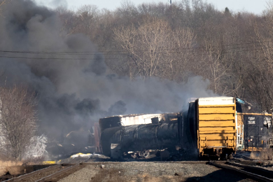
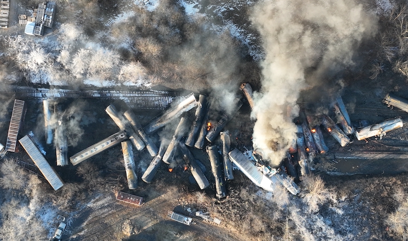
So by now, you have all probably heard about, and seen images of, the dramatic derailment of Norfolk Southern train 32N in the town of East Palestine, Ohio.
On February 3rd, 2023, at about 8:54pm, NS train 32N-02 hit the ground. An axle bearing, on car 23 of 149, overheated and failed, causing 38 cars to derail and catch fire. Five of these cars, cars 28 through 31 and car 55, were loaded with ‘Stabilized Vinyl Chloride,’ a chemical used principally in the production of PVC piping.1,2 The train crew–an engineer, conductor, and conductor trainee–tied (applied) handbrakes on the first two cars, and uncoupled the leading two locomotives to get them to safety, while first responders attended to the fire.1 However, after the fire was extinguished one of the vinyl chloride tank cars continued to increase in temperature, leading responders to fear an explosion. Thus, a “controlled release” of all the vinyl chloride cars was authorized, and proceeded on February 6th.
Now, if you’re like me, you want to know everything about what happened. Why did this go catastrophically wrong? Why did they have to release the vinyl chloride in a “controlled burn”? What’s so bad about burning vinyl chloride? Where did the cars come from and how did they get here? And of course, how can we prevent this from happening ever again?
Making Plastic
First, let’s talk chemistry.
Vinyl chloride, or Vinyl Chloride Monomer (VCM) is the primary component of polyvinyl chloride, or PVC. VCM is turned into PVC by way of a polymerization reaction. The actual chemistry behind it is beyond the scope of this blog post, but the important part is that polymerization is an exothermic reaction, i.e. it releases more energy than is put into it. In production facilities, this is simply a fact of life, and is dealt with by cooling the pressure vessels that contain the reaction. Vinyl chloride itself is produced via a two-step process; the chemistry here is a bit more involved, so bear with me. First, the chlorine halogenation of either ethylene, C2H4, or ethane, C2H6, results in a substance commonly known as Ethylene Dichloride, or EDC. EDC is then ‘thermally cracked,’ resulting in vinyl chloride and hydrogen chloride gas. This reaction, unlike the polymerization of vinyl chloride into PVC, is endothermic, and requires heating, rather than cooling, to progress safely. (Older methods used acetylene as the hydrocarbon component, which is significantly more volitale than ethylene or ethane.)
PVC was first commercially produced by the B.F. Goodrich company in 1926 (though the chemical itself was discovered almost a century earlier)3. Most PVC production today is undertaken by a single company: Shin-Etsu Chemical, a Japanese chemical concern that produces a dizzying array of plastics, industrial chemicals, rare earth magnets, silicone, silicon–even caustic soda (or Sodium Hydroxide for the chemically-minded among you). Though about half of world production of PVC takes place in China, it’s divided among various concerns that individually account for significantly less market share than Shin-Etsu, with a hefty 30% of global production. According to the European Council of Vinyl Manufacturers4, over 40 million metric tonnes, or 88 billion pounds, of PVC is produced worldwide every year; an equivalent amount of VCM would be enough to fill almost four hundred sixty-four thousand (464,000) tank cars of the type that derailed in East Palestine.
Now, while PVC is quite stable and non-toxic, vinyl chloride is distinctly not. In its gaseous form, it’s flammable and carcinogenic, with a maximum safe limit of 500 parts-per-million (ppm). It’s most commonly stored and transported, however, as a liquid under pressure, which brings its own risks. The flash point, at which enough liquid VCM can vaporize that it can be ignited, is -108.4 degrees Fahrenheit–lower than the lowest temperature ever recorded in the United States5. Thus, any leak from a pressurized vinyl chloride-containing vessel could turn into a Boiling Liquid-Expanding Vapor Explosion–a BLEVE.
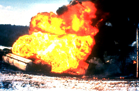
BLEVEs are the nightmare scenario for first responders. They occur when a pressurized vessel containing a liquid–one that would normally be a gas at atmospheric temperature–is abruptly released. The rapid drop in pressure lets the liquid boil to vapor almost instantly, and since gases take up more volume than liquid does, this tends to cause the pressure vessel to explode. With vinyl chloride, the risk is even more significant: the heat produced by a BLEVE could cause VCM to undergo an uncontrolled polymerization reaction, leading to more explosions; vinyl chloride gas could also react with elements in the environment it’s released into, forming peroxides that may themselves spontaneously combust. And if all that wasn’t enough, when it burns, vinyl chloride decomposes into hydrogen chloride, carbon monoxide, and small amounts of phosgene gas. You’ve probably already heard that phosgene was used in World War I as a chemical weapon, which is true6–it was apparently significantly deadlier than mustard gas, though not as significant in the public memory–but in fact it was often used in conjuction with chlorine gas, as chlorine helped spread the denser phosgene gas over a broader area. A vinyl chloride fire could thus turn a significant area into a horrific WWI battlefield in relatively short order.
This brings us back to the derailment. February 3, 8:55pm: Fire engulfs 5 tank cars full of vinyl chloride. 68 firefighting crews respond, but are prevented from extinguishing the fire7. The fire has been more-or-less put out by Monday, but one of the tank cars continues to show an increase in temperature, suggesting spontaneous polymerization is taking place; a ‘controlled release’ is undertaken to avoid a BLEVE1,8. The idea is that being able to control the burn of vinyl chloride will prevent most of the toxic chemicals from being dispersed randomly, and thus affecting more people than absolutely required–even though it will still release phosgene, hydrogen chloride, and carbon monoxide. The first responders, and Norfolk Southern agents, must have decided that was the only safe course left to them at this point. But surely there must have been a way to avoid poisoning the Ohio River basin at all, right? 40 million tonnes of PVC are produced every year, and this is the first time (to my knowledge) that vinyl chloride has been leaked in a derailment of this magnitude. So why did it happen now?
Bearings
First, we have to talk about bearings.
Bearings, as the name might suggest, are the crucial final linkage between railcar and wheel. Railcars ride on (usually) two sets of bogies, or ‘trucks’ in North American vernacular, that are not permanently affixed to the carbody itself but simply held in place by the weight of the car.

The center pin, in the above image, is what the railcar sits upon (there’s a compatible sleeve on the car, of course). The weight is then distributed via the bolster to the side frames, which join the bolster to the axles and contain springs to cushion the ride. The bearings are the parts of the axle that these side frames rest upon, and they transmit all the force from the weight of the railcar to the axle, and thus the wheels themselves. Simple enough, right?

This is the most basic form of bearing, a plain bearing. Plain bearings were used on practically all types of railroad equipment until the 1930s; while they require frequent maintenance and lubrication and are susceptible to catastrophic failure, they’re cheaper to manufacture, and railroads are highly resistant to change. The journal housing, or journal “box,” around the bearing in the image above would typically be filled with oil-soaked rags to ensure a smooth ride. If not properly lubricated, the friction of the side frames bearing down on the axle as it turned would cause the bearing to heat up and often catch fire, hence the term “hotbox.” These were common enough that a primary duty of the trainmen in the caboose was to watch out for the tell-tale smoke from a developing hotbox, and alert the engineer in the locomotive far ahead if one was detected. If you were lucky, they would get the train stopped before it melted the axle off and derailed the train.

Roller bearings were introduced to the railroading in the 1930s, primarily as an extra-cost option for extra-fare trains. Most railroads, beginning with the Santa Fe, began equipping their passenger train fleets with roller bearings first, leaving their freight cars practically untouched. Plain bearings produce significantly greater rolling resistance than roller bearings, and that resistance increases exponentially with speed, so initial applications of roller bearings were limited to trains that a) had relatively consistent makeup, and b) made money by dint of their speed. Passenger trains fit the mold to a T, with early streamliners having fixed trainsets instead of individual cars; time-sensitive freight, like fresh fruit or mail & express, also saw some improvement. Eventually, however, railroads realized that the reduced rolling resistance on a train made up of entirely roller-bearing-equipped cars meant that more freight could be hauled with the same amount of power (or, more accurately, the same amount of fuel consumption). Thus, orders for new freight cars with roller bearings took off after World War II, and the last new plain-bearing equipped car rolled off the line in 19689. Plain-bearing-equipped cars were still allowed in interchange–i.e., exchanged from one railroad company’s tracks to another company’s–until 199427, but a 1979 regulation prohibited operation of any railcars more than 50 years old unless several strict provisions were met10, and a surge in railcar manufacturing in the 1970s and 1980s14 ensured that the vast majority of freight cars in service since 1980 were roller-bearing equipped. [Note: the interchange rules are maintained by the Association of American Railroads, an industry trade group that serves both as a self-regulating body for American railroad companies, and a lobbying group for their interests. There is no Federal regulation specifically concerning interchange of freight cars between different railroad companies.]
Roller bearings are sold as self-contained units, often as part of entire wheelsets (i.e. wheel, axle, and bearings already assembled). The bearings are pre-greased at the factory, with enough lubrication to last the projected lifetime of the bearing, and then sealed to prevent foreign contaminants from leaking into the journal, and grease from leaking out28. If grease is seen to be leaking from a roller bearing in service, it is a Federal defect10 and the car must be taken out of service until the bearing is repaired or replaced.
Radios, Computers, and Jobs
As radio communication improved and computers were developed throughout the latter half of the 20th Century, railroads began to adopt the new technology, and, although relatively slowly, adapt their business around it. In the 1950s, dieselization had made the position of Fireman obsolete, as the diesel had no open flame to tend and no boiler to protect (though the actual title of ‘fireman’ remained in use long after dieselization was complete, as firemen were essentially ‘apprentices’ to engineers). Similarly, in the 1980s, the radio and the computer would make the caboose and associated Brakemen obsolete. Instead of having a whole railcar on the back of every train housing two or three men in order to a) apply the emergency brake on the end of the train if need be, b) signal to other trains and employees where the end of this train was (by way of lanterns hung from the end corners of the caboose platform), c) and report the brake pipe pressure to the engineer during a brake test, you could have a computer and a radio do it all. A little box on the end of the last car of the train, officially called the End-of-Train Device (EOTD) but often referred to as the FRED (Flashing Rear-End Device), could monitor the air pressure via a computer and talk to a little computer-and-radio-box in the cab of the locomotive (officially the Head-of-Train Device, but often nicknamed ‘Mary’ or ‘Wilma’) via radio, and the engineer could simply glance at it whenever they needed to know the air pressure at the rear of the train. A little toggle switch, also connected to the computer-and-radio-box, could “dump the air” in an emergency, and a blinking red light, instead of a red-tinted lantern, would indicate the end of the train.

Radios and computers weren’t limited to boxes on the train either. Back in the 1950s, having a radio on an engine or caboose was noteworthy enough that many railroads had a “Radio Equipped” stencil emblazoned on units so equipped, but by the 1980s radios had become so cheap and computers so widespread that they could be installed alongside the tracks just about anywhere, even in the most remote locations. And instead of relying on the inevitably fallible human senses to detect issues with a train, you could simply have the computer do it, by way of a variety of inexpensive sensors. Hotboxes and hot wheels–the latter caused by misapplied or faulty brakes–could be detected by a thermometer, and anything dragging on the ground could be caught by a sturdy pressure sensor. The computer would then determine if anything that triggered the sensor was actually an issue, and if it was, it would send a message over the radio straight into the cab of the locomotive. The engineer no longer had to keep an eye out for a red flag being waved from the caboose 100 cars back; now, a robotic voice from the cab radio–mere inches away–could simply announce exactly what was wrong as the train passed by.

This was great for the railroad companies too. Instead of paying for a whole extra person for every train whose job was just to look out the window for 12 hours, you could buy a single computer and a single radio that would scan every train and automatically tell you if something went wrong with a train. Of course, you couldn’t have just one, as problems might develop over the course of a trip, so most railroads installed these Wayside Detectors at 10-to-20-mile intervals. They didn’t eliminate labor costs entirely either; railroads still had to pay some people to fix all these computers and radios, and electronic repair requires a lot more formal education than brakemen usually had, but the computers and radios were fairly reliable (mostly because they weren’t terribly complicated), and paying one or two expensive people to monitor and fix the detectors on a couple sections of line was still a hell of a lot cheaper than paying five or six people to crew every train that ran over the line.
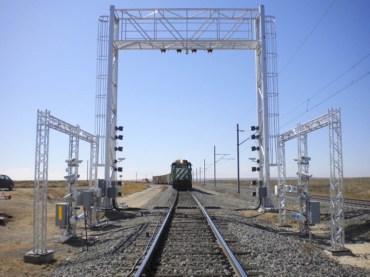
These computers with radios attached gradually got more sophisticated, of course. Advanced lineside scanners, like the one pictured above, can alert crews or managers to defects that even a thorough inspection might miss. But computers, unlike humans, will do exactly as they are told and no more, meaning that if any defect is detected a warning will be transmitted. And since railroad operating rules require all trains to stop and inspect the train whenever a detector transmits a warning, so-called “false stops”–wherein a train stops to inspect a detector warning but fails to find the indicated defect–are remarkably common, with Norfolk Southern experiencing more than 750 incidents in 201211. NS managers, particularly in the era of “Precision Scheduled Railroading,” find these false stops so objectionable that the railroad has a dedicated helpdesk that allows train crews to ignore detector warnings if, to quote a ProPublica expose on the policy, “information is available confirming it is safe to proceed”29. What this information is, Norfolk Southern has declined to say.
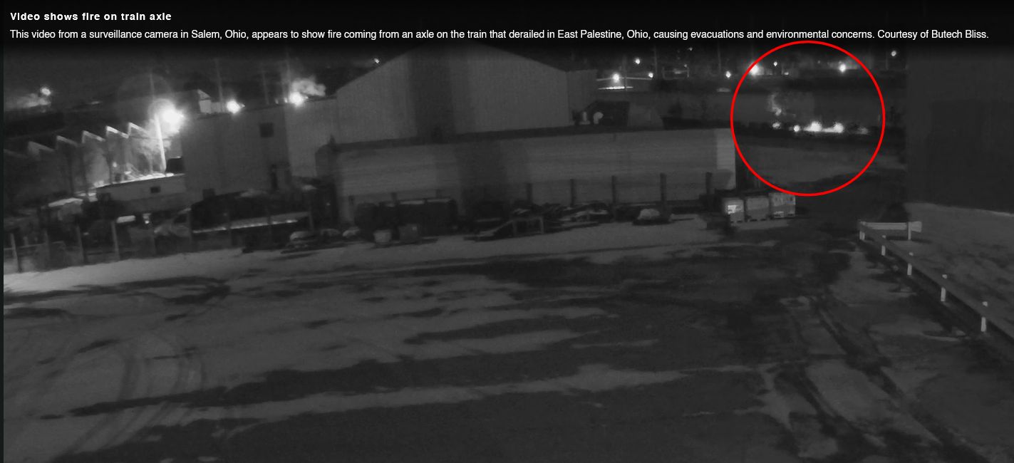
Another approach to reduce false stops is to raise the temperature threshold at which hotbox detectors will transmit a warning. Some railroads set that threshold at 90 degrees Fahrenheit above the ambient temperature, but Norfolk Southern has their threshold set to 170 degrees total for a “non-critical” bearing, i.e. one for which the train must stop and inspect the bearing, but not necessarily set the car out of the train12. Thus, when the now-infamous 32N passed the detector in Salem, Ohio (milepost PC 69.013), and the axle that would eventually fail was recorded at 103 degrees above ambient, the detector did not transmit a warning. The high temperature for that day was 24 degrees, and 130 degrees total is well below NS’s warning threshold. The detector in East Palestine, milepost PC 49.81, measured the same axle at 253 degrees above ambient12, but by then it was too late and the axle was already as good as gone. (NS does have a provision for checking the bearings on both sides of the axle against each other, but it’s not clear if that functionality would have helped in this case.)
Of course, en-route scanning by automated systems can only do so much. The first line of defense for any kind of defect is the “car knocker,” or simply “carman.” They get their nickname from the days of plain bearings and cabooses; they would often tap, or ‘knock,’ ball-peen hammers on the wheels of every car to check for defects that might be impossible to see, but produced a distinctive sound15. Federal regulations stipulate that, before any freight car is allowed to move “in a train,” an inspection must be performed to make sure it’s safe to move10, and the “qualified persons” that must conduct said inspections are, almost without exception, the carmen. These pre-departure inspections cover practically every inch of the car, including the entire brake system, all of both trucks, the couplers, the frame, etc10. The regulations don’t require additional inspections until the car is put into another train, but thorough brake tests and inspections are required at 1,000-mile intervals16, and any critical defects are usually readily apparent to the carmen conducting such tests. That is, if they’re given enough time to complete them properly.
Stop That Train
Let’s talk about brakes.
At its simplest, a train brake is just a piece of hard material that is placed against the wheel or the car, and uses friction to slow the wheel’s rotation. The great benefit of steel rail-based transportation is also its greatest shortcoming; steel acting on steel produces relatively little friction. This gives rail transport its high fuel efficiency per weight and distance, but it means railroads must be constructed with lower grades (few American railroads have grades above 2%, and only the steepest exceed 3%32), as well as making rail vehicles difficult to stop.
The earliest brake systems were extremely primitive mechanical systems. Mine carts in British coal mines in the late 1700s had a lever that would press a wooden block against one wheel, slowing the cart. This required a man to ride the cart to operate the lever, of course, and if the brake failed to slow the cart, it would end in disaster.

As the 1800s began, someone had the bright idea to link these carts together behind a steam engine on wheels, rather than using horses or even just manpower. The basic manually-operated “handbrake” remained the only method of stopping, even as those carts got larger and heavier and began to morph into the modern railcar. Instead of a simple lever, though, the wheel-type handbrake was developed: in conjunction with rooftop running boards, this made it easier for a single brakeman to apply the brakes on multiple connected cars. The primary factor determining actual braking effort, however, was still how hard you could physically crank the brake wheel, and braking an entire train by hand was a slow process; each car had to have its handbrake cranked as far as possible before the brakeman could move on to the next one.

Brakemen were thus a critical occupation of railroading in this period. Since no system yet existed that could apply brakes throughout the train automatically, engineers had to blow a whistle signal that told the brakemen it was time to clamber onto the rooftops of the cars, while the train was in motion, to start braking the train. This was not only incredibly dangerous, but also limited trains’ size and speed and gave rise to the modern caboose: having brakemen walk the cars from both ends of a train and apply the brakes simultaneously meant that the train would stop twice as quickly, but trains could not consist of more cars, nor travel faster, than two or three brakemen–one in the middle, as well as one each in locomotive and caboose–could reasonably brake in time to stop30. (Having a brakeman in the middle also reduced slack action, but this was the era of “link-and-pin” couplers and freight trains of rarely more than 20 cars, so the effect would have been negligible. We’ll touch on this more in a moment.)

George Westinghouse was born in 1846 to a New York machine shop owner, George Westinghouse, Sr., and his wife Emeline. In 1862 he enlisted in the New York National Guard and fought for the Union until the war’s end; shortly thereafter he filed a patent for a ‘rotary steam engine’, a device he had invented at only 19 years old31. But agricultural machinery was not to be his domain. After patenting a couple of track-related devices, Westinghouse witnessed a horrific collision near Schenectady, New York, wherein two trains were about to meet head-on; the crews of both trains attempted to stop, but the lengthy process of applying each brake by hand meant that, even though the crews could see each other, they were unable to prevent the collision. Westinghouse set his mechanically-gifted mind to the problem, and by April of 1869 he had created the basic version of the modern automatic air brake.
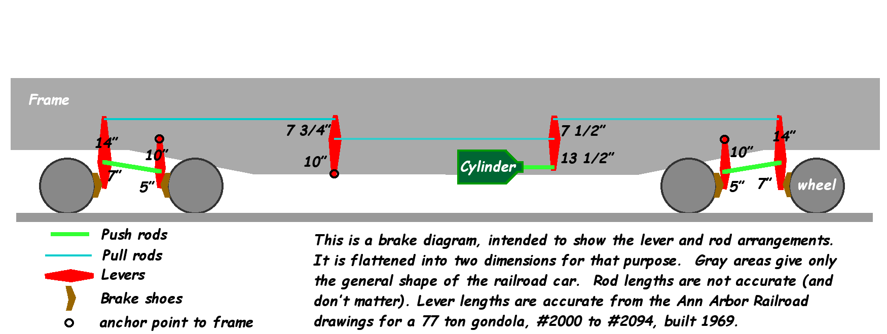
His first design was what’s now called a “straight air” system. Pressurized air would be pumped from a compressor in the locomotive through a brake pipe along the length of the train. When the engineer wanted to apply the brakes, he would increase pressure in the brake pipe, and that pressure would act on a brake cylinder (shown above in green), which would then act on a series of levers and rods that pressed the brake shoes firmly against the wheels. It worked reasonably well, but because the brake pipe had to be pressurized in order to apply the brakes, the resting state of the system–i.e., unpressurized–was “brakes released,” and it was quickly discovered that, if the handbrake was not applied correctly (or at all), the car could roll away unattended. Further, in actual operation it was found that the brakes would apply unevenly throughout the train, with the cars at the front–nearer the locomotive, the source of all the pressurized air–applying full braking force before the cars at the rear had begun to apply at all32. The slack action that this caused–that is, the ‘movement of one car in relation to adjacent cars,’ enabled by the lateral play each coupling necessarily had–was so violent that trains of more than 25 cars were impractical. Needless to say, customers of the new Westinghouse Air Brake Company were frustrated by this limitation, so in 1873, Westinghouse devised an improved system.

Instead of requiring air pressure to apply the brakes, now the train line was pressurized in order to release the brakes. Thus, if a brake hose separated en route, the air pressure would drop in the brake system on both halves of the train, and both halves would stop automatically. Westinghouse accomplished this by adding two components to his initial ‘straight air’ system: an auxiliary reservoir on each car, that would be kept pressurized during normal operation; and the triple valve–basically a slide valve with three openings, so named because it performed three functions. The triple valve allowed: (1) pressure from the auxiliary reservoir to flow into the brake cylinder, applying the brake; (2) pressure in the brake cylinder to flow out and vent to atmosphere, releasing the brake; and (3) pressure from the brake pipe to flow into the reservoir, thereby “recharging,” or repressurizing, the reservoir33.
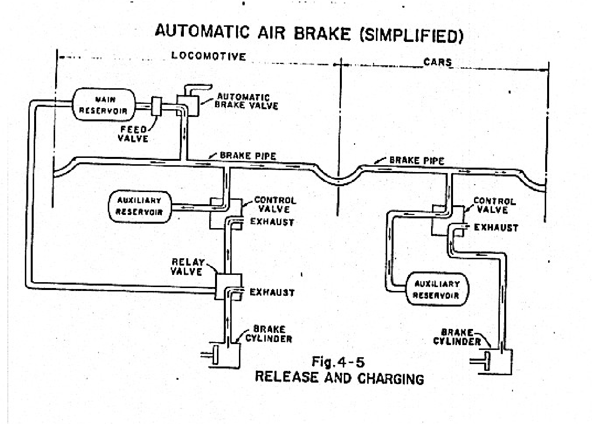
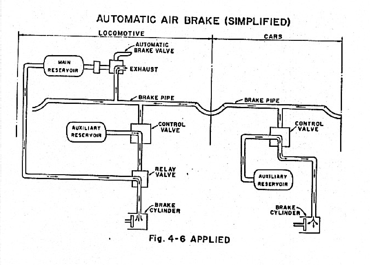
Both of the above photos are taken from https://wplives.org/forms_and_documents/Air_Brake_Principles.pdf
Any change in train line air pressure is detected by the valve, and, depending on the difference between the pressure in the reservoir and in the brake pipe, the valve will move to make the brakes apply or release. If the pressure in the line drops below that of the auxiliary reservoir, the difference in pressure sucks the valve closed, blocking off the brake cylinder exhaust port and forcing the pressure in the reservoir to drop, matching the lower pressure in the brake pipe. The only place for the pressurized air in the reservoir to escape is through the brake cylinder, which forces the cylinder outward, thus applying the brake. If the pressure in the brake pipe rises above that of the reservoir, the valve will be pushed open, and air from the brake pipe will flow into the reservoir until it reaches the same pressure as the pipe, while the air in the brake cylinder is freely exhausted.
There’s a catch to this though. The brake cylinder and the auxiliary reservoir have significantly different volumes–a ratio of 1-to-2.5, specifically35–and if you paid attention in high school chemistry, you’ll remember that, for all else held constant, a gas forced into a higher volume means it will have experience proportionally lower pressure. Thus, if the engineer reduces the brake pipe pressure by 10 psi–or in railroad jargon, “makes a 10-pound set”–the triple valve will be sucked closed until the auxiliary reservoir is also reduced by 10 psi, which means the brake cylinder will produce 25 psi of braking force. Further reductions will have a similar effect, eventually reaching a point where the auxiliary reservoir and brake cylinder will “equalize,” i.e. reach identical pressures; beyond this point (which is 64 psi on 90-psi systems, the most common in use today), any further reduction in brake pipe pressure will not have any effect on the actual braking effort being applied. This is due to the fundamental nature of compressible gases.
Pressure is defined as force per unit of area, so a container with high pressure is exerting more force on the molecules of gas within its inner surface area than a container with low pressure. If you were to connect these two containers together (assuming they contain identical gases), the force acting on each molecule in the high pressure container results in those molecules having a vastly higher velocity than the molecules in the low pressure container, so even though the actual movement of each individual molecule is entirely random, more of the faster molecules end up bouncing into the lower-pressure container than vice versa. Once inside the low-pressure vessel, the fast molecules start to bounce off of its walls, exerting much higher forces on it than the slow molecules that were in the low-pressure container to start with could even dream of–and the random movement of the molecules means that some of the fast ones bump into the slow ones, and accelerate their movement, which then causes them to bump into other slow molecules, and so on and so on until all the molecules have the same average velocity, and thus the same force exerted on the inside of both containers, and the same pressure. All this means that, when the pressure in the auxiliary reservoir and the brake cylinder on a train are identical, there’s no force available to push the triple valve closed, and venting the brake pipe becomes just a waste of pressure.
Modern airbrake systems are usually pressurized or “charged” to 90 psi35. This allows for a fairly wide range of “service reductions,” i.e. controlled reductions in brake pipe pressure that are used for gradual slowing and stopping, to be made before exhausting the above-described capacity of the air system to provide braking force. The initial design of the system vented air through a single hole in the ‘control valve,’ at the engineer’s control stand; this caused the same violent slack action as the straight air system described earlier, as well as taking a long time to apply all the brakes (though with the benefit of being “fail-safe” rather than, in some cases, “fail-deadly“). Enter the quick service valve. A tiny reservoir is added to the control valve which is sized in relation to the brake pipe on the car, and when a reduction of up to 6 psi is triggered in the brake pipe, the reservoir quickly siphons off 6 psi from the car’s auxiliary reservoir. This allows each car to begin the application of brakes much more quickly than before. If a reduction of more than 6 psi is made, however, the quick service valve is bypassed, and the triple valve on the car acts normally; thus, all modern “air brake and train handling” rulebooks specify making an initial reduction of no more than 6 psi33.
Emergency applications were another issue. Sometimes, the quick service feature would fail to act properly when triggered by a rapid loss of pressure; thus, new “vent valves” were added to longer cars and locomotives, and new control valve designs were mandated that had an emergency application vent–a “big hole,” which became railroad slang for putting a train into emergency braking. The auxiliary reservoir was also enlarged and subdivided into “service” and “emergency” portions; if brake pipe pressure was reduced rapidly, the emergency portion would trigger, adding extra air to the reservoir in order to equalize the brake cylinder to 77 psi (on a 90-psi system), giving the train extra stopping power when it’s absolutely needed.
This new Westinghouse system was a success, and the above improvements made shortly after its introduction made it even more so. It was relatively low-cost and low-maintenance, especially compared to other systems of the day, and the reduction in casualties that it brought about (combined with the automatic coupler, which appeared around the same time) was so significant that in 1893, Congress mandated the installation and use of automatic brakes on every locomotive, and “a sufficient number of cars . . . that the engineer on the locomotive . . . can control it without requiring brakemen to use the common hand brake”36. New and improved brake stands in the locomotives, first in the steam engine and then in the diesel-electric, allowed for finer control of each actual reduction, and were more reliable and easier to use33,34. And finally, shortly before the 20th Century came to a close, the advent of the micro-processor promised to provide the next quantum leap in braking technology: ECP brakes.

ECP brakes, or Electrically-Controlled Pneumatic brakes, consist mainly of a computer mounted on each individual railcar that is then linked to the pre-existing air brake system. Shortly after the derailment of 32N, several news outlets claimed that ECP brakes would have either fully prevented, or at least lessened the severity, of this derailment by cushioning the slack action caused by the emergency application24. We’ve already seen how applying the brakes on a long train doesn’t necessarily mean every car begins to brake immediately, as each triple valve must adjust to the reduction in pressure and each auxiliary reservoir must force air into the brake cylinder. Releasing the brakes, however, can take much longer; a 90-car train might take 34 minutes on a good day32, and longer trains, or trains operating in extremely cold weather, might take hours to fully charge all the brakes. Further, if the engineer tries to release and re-apply brakes too quickly, the reservoirs in the cars won’t have enough time to settle, and thus will not exert nearly as much braking effort–or, in some cases, may even begin to release35. The advent of Distributed Power Units (DPUs)–locomotives placed in the middle or rear of trains, controlled from the lead locomotive via radio remote–has helped somewhat with some of these issues, providing (among many other things) an additional air compressor further back in the train. But many railroad companies have chosen to simply increase their average train length to the limit of the DPU, leaving the trains’ brake systems in the same quandry they were before.
ECP brakes seek to remedy this by way of a computer. Now, instead of the brakes being activated at the speed of sound via a mechanical valve and air pressure, a micro-computer on the locomotive transmits a message at the speed of light to the micro-computers installed on each car. That electronic message is the signal to apply or release the brakes, rather than the propogation of air pressure, so every car in a train receives the same signal almost instantaneously instead of having to wait several minutes. Though expensive–on the order of $4000 to retrofit an existing railcar, and over $40,000 per locomotive37–ECP brakes completely eliminate the slack action that traditional systems are known for, allowing heavier trains to stop much more quickly. And since the valve to trigger a brake application is electronic, the brake pipe can continuously charge the reservoirs on every car, meaning full braking effort is always available38. And if all that weren’t enough, those micro-computers are powerful enough to do other things too, like monitor the health of the car’s braking system, or even other parts of the car like, say, wheel bearings, providing an invaluable early warning system with pinpoint accuracy. Of course, it only works if railroads actually install the system on their equipment.
Cut to the Bone
Precision Scheduled Railroading, or PSR, has been written about at length in a bevy of publications. Some laud the idea, others scoff at it, and some find the whole thing preposturous. But what, exactly, is it?
At its core, PSR is a philosophy of railroad management that emphasizes asset utilization above all else. Instead of train velocity across a railroad’s network, PSR, the brainchild of E. Hunter Harrison, focuses on car velocity, and tries to increase it. In most implementations, PSR also prioritizes lowering the Operating Ratio–the ratio of revenue generated by a company’s operations to the cost of those operations–often far below typical ranges for railroads, or even transportation companies in general. As my old professor and mentor, Dr. C. Tyler Dick of the University of Illinois at Urbana-Champaign, wrote in an article in Trains magazine, PSR essentially acts as a combination of two nominally opposed operational philosophies: “hold for tonnage,” and “run on schedule”39. The “hold for tonnage” approach is pretty much just what it sounds like: a train will be “held” at its initial terminal (i.e. train yard) until enough cars for the train’s end terminal filter into the initial yard to make running that train “economical.” The exact definition of “economical” is usually determined by various Byzantine calculations done at the railroad’s head offices. The scheduled approach is the more traditional railroad approach, wherein trains are run according to a fixed schedule no matter the amount of tonnage that train is projected to haul. This leads to a very consistent operation–“you could set your clock to it,” some might say–but also leads to things like this:

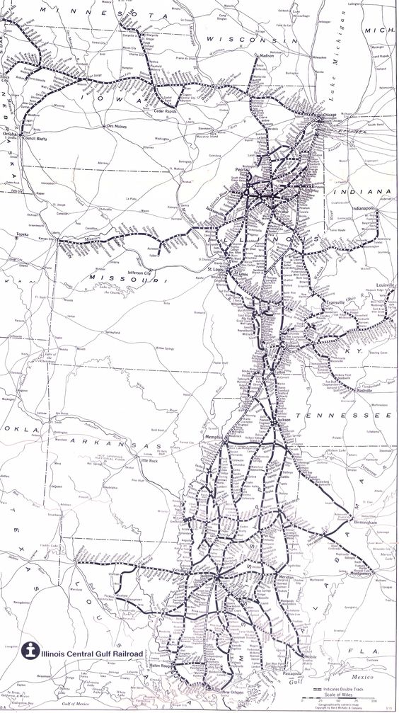
PSR aims to balance the two philosophies, by running very long trains, but on consistent schedules, eliminating the randomness of the single-commodity “unit train,” which are often run on an “as-needed” basis and are thus difficult to predict and plan around. PSR was first truly adopted, at Hunter Harrison’s behest, by the Illinois Central in 1989. The IC was one of America’s oldest railroads, operating a unique north-south mainline from Chicago to Memphis and New Orleans as well as branches as far afield as Omaha, Louisville, and Shreveport. IC had, like other major railroad companies in the midwest, found itself on poor footing as private railroads struggled to survive against trucking companies, most of which operated on the publicly-funded Interstate Highway system and thus could offer bargain-basement rates on time-sensitive shipments that railroads couldn’t, or chose not to, match or beat. Either way, the IC had spent much of the 1980s selling thousands of miles of trackage that was deemed ‘unprofitable,’ and by the time Hunter took charge, it was a slimmed-down, 3,000-mile trunk line between Chicago and the Gulf of Mexico.

As implemented on the IC, PSR worked remarkably well, turning the road from a run-down backwoods pike into a system strong enough to attract interest from the massive Canadian National system to the north, which acquired the smaller road in 1999. Hunter was promoted to Chief Operating Officer of the new combined system and attempted to work the same magic at CN–but CN’s less-concentrated network meant more operational difficulties. Despite that, the recently-privatized CN saw its operating ratio plummet, from 89% at privatization in 1995 to 70.4% in 2000, a trend that continued to an all-time low of less than 60% in 201540. That means that more than 40 cents of every dollar the company earned in revenue was pure profit. The shareholders of CN, naturally, were overjoyed; many of them owned shares in other railroads too, and after the economy had recovered sufficiently from the 2008 recession, there were calls for PSR to be implemented at other railroads. Canadian Pacific (CP), CN’s only real competitor in Canada, was next to feel Harrison’s influence after “activist investor” Bill Ackman’s hedge fund, Pershing Square Capital Management, won a proxy battle for control of the railroad in 201241. Three years later, CP had slashed its operating ratio to just above 60%, not far from CN’s. Two years after that, Hunter assumed the top spot at CSX, and seemed to be on track to make similar “improvements” when he abruptly died in office, leaving Jim Foote in charge of the railroad.
It was around this time that Harrison’s influence began to be felt throughout the American railroad industry. No sooner had Harrison’s death dropped from the front page of major industry publications than Norfolk Southern (NS) and Union Pacific (UP) publicly announced their own implementations of ‘PSR’–but now, instead being seen as an operational philosophy that could produce good financial results, PSR became a buzzword, a cudgel used to justify lowering operating ratios and boost share price by any means necessary. As a result, workers at all the railroads operating under the PSR model faced massive layoffs, insane workloads, and were often instructed to ignore safety procedures in order to meet arbitrary deadlines.
For example, NS car knockers before PSR had worked out that it took about 3 minutes to do the FRA-mandated pre-trip inspection on a single car. NS managers then issued a requirement for carmen to spend only 2-and-a-half minutes inspecting each car; a bit tight, but doable. But since PSR’s reign, that time has shrunk dramatically, to less than 90 seconds on today’s NS17. That’s hardly enough time to look over one side of one car, let alone inspect the whole car AND write up any issues that are found.
One of the main ways PSR gets car velocity up is by pushing them through major yards faster, i.e. reducing “dwell time.” In the 5 years before PSR made its debut on the system, NS averaged about 32 hours of dwell time per car at its major yards18. After PSR, that average dropped to 25 hours. NS also promised to fire 3,000 employees between 2019 and 2021, many of whom were mechanical department personnel. Sure it helped the operating ratio, but now instead of inspecting 300 cars per day, the carmen who remained had to inspect up to 1200 per day17. Many were even told to falsify reports or ignore obvious defects in order to speed up the process of getting the cars through the yard, with one UP car knocker telling The Guardian that her manager had explicitly told her not to ‘bad-order’ cars with leaky bearings19. Though the official NTSB investigation won’t be published for a while yet, I wouldn’t be surprised if they found that a proper inspection could’ve detected the bearing that failed on 32N, and such an inspection was pushed off by management, or just not done thoroughly enough, in order to get the train out of the yard faster and not incur a penalty from management.
It’s not just the freight cars that need inspections, though. The defect detectors we discussed earlier, those computers with radios attached, also need periodic maintenance (really, what doesn’t?) and PSR cuts affected those workers too. The Pittsburgh Division, in which the Ft. Wayne Line through East Palestine is located, had, prior to PSR and COVID-19, five people assigned to detector and signal maintenance–a position NS blandly calls an “Electronic Leader”20. When 32N hit the ground on February 3rd, it had zero. Not one person in the entire 1,300-mile division was dedicated to making sure the instruments crucial to catching critical en-route failures were properly functioning. And all because NS shareholders had to squeeze another few million dollars of profit out of the railroad, instead of actually running it.
But despite all that, even if 32N had a rushed inspection and even if no one was actually checking to make sure the detectors were properly detecting, there was one final line of defense: the train crew.
Steps to Disaster
32N was not a high-priority train. Train symbols–callsigns, essentially, that denote the routing of a train and what kind of cargo it typically hauls–vary greatly between railroads, but on NS, these symbols are fairly straight-forward. Every train is identified by a three-character “number.” The first digit denotes priority; trains with a ‘1’ are “general freight” trains, hauling just about any commodity over longer distances (usually from one division to another). Numbers starting with ‘2’ are actually the highest-priority trains, almost exclusively containers, trailers, and automobile carriers (autoracks) that move on the fastest schedules NS offers. Then come the 3xx-series trains, which tend to be slower, shorter-distance trains, often operating within the bounds of a single division. Railroaders sometimes call these “dog trains,” and they’re rarely a coveted assignment. Train 30N, for instance, departs daily from the Terminal Railroad Association of St. Louis’s massive yard in Madison, IL, and lopes up the Brooklyn District to the smaller (but still enormous) yard in Decatur, IL, where it terminates. The whole trip, 105 miles by rail, could take most of a 12-hour shift.
32N was similar, operating essentially as a giant rolling vacuum cleaner for all the yards along its path. This path, however, was much longer than 30N’s, stretching from the eastern bank of the Mississippi River in Madison to the western shore of the Ohio in Conway, Pennsylvania, with scheduled stops in Decatur, IL; Lafayette, IN; and Fairlane, Ohio (which appears to have been a support yard for the Ford plant just west of Lorain, OH, and now seems to serve as a staging point for autoracks moving from points west to the General Motors plant in Sterling Heights, Michigan). Before PSR consolidated trains together (in an effort to cut costs by paying fewer crews and using fewer locomotives), 32N was actually two separate symbols, and–as best I can tell from the limited data I have–those trains were: train 10E, handed off directly from the Union Pacific at the tiny town of Sidney, in eastern Illinois, and taken to NS’s massive yard in Bellevue, Ohio; and train 14K, which took cars from Bellevue to the similarly huge Conway yard near Pittsburgh21. 32N also likely handles some traffic from St. Louis through Decatur, IL, which was also split into two trains; train 302 between Granite City, Illinois–site of NS’s own yard in the St. Louis area–and Decatur, and train 146 forwarded traffic from Decatur to Bellevue. At some point before the incident, 10E was rescheduled, coming straight from UP’s big yard in North Little Rock, AR, and running through to Bellevue. 14K and 146 have since been abolished, and the ‘302’ symbol is now a train from Bellevue to Fort Wayne, Indiana. Norfolk Southern’s PSR-styled “TOP21” operating plan is the source of most of these changes; “TOP|SPG,” a sort of ‘PSR Lite’ designed by new CEO Alan Shaw and implemented by similarly new COO Paul Duncan, rolled out in June of 2022 and made additional changes to schedules system-wide.
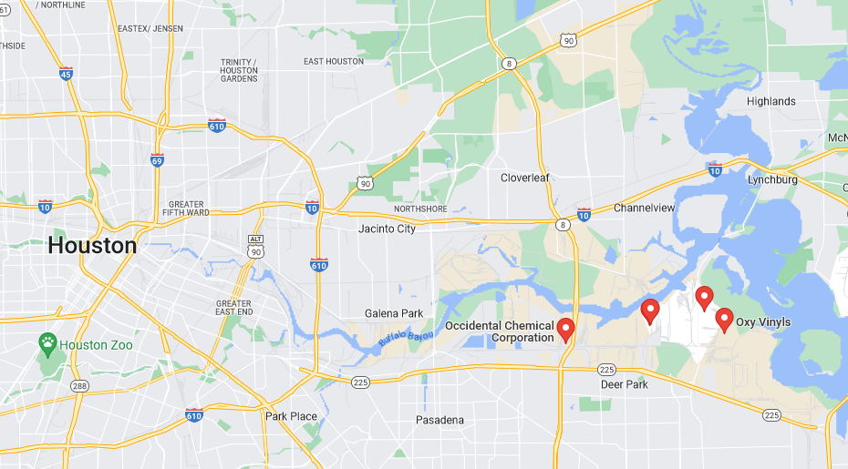
Based on the partial manifest of 32N that was released shortly after the derailment, and statements made by NS employees familiar with the train to Vice, I believe the vinyl chloride on the train was produced in Texas2,22. Occidental Chemical owns three of the railcars involved in the derailment, and has a major presence in Houston, as shown below. While Shin-Etsu Chemical also has two facilities in the state and is a larger global producer, I don’t believe they produced the vinyl chloride that burned in Ohio (though we’ll likely never know for sure). But Texas, and Houston in particular, is known for its immense production of nasty petrochemicals like vinyl chloride, and if it’s shipped to Pennsylvania on NS, then 32N is almost certainly the train that takes it there. Despite whatever bloviating NS officials might perform to the contrary, specific train symbols can quite easily be recognized from the type of freight they carry22. Anyone with a radio scanner and enough time can easily deduce which trains run and generally when, and with a quick Google search, they can also figure out what’s on them. And, as Fred Frailey’s excellent book Blue Streak Merchandise exemplifies, railroad marketing departments often market specific trains and their schedules to customers, especially if they’re fast.
In addition to its many chemical plants, Houston is a major railroad hub, with 3 Class I railroads and several shortlines serving the sprawling metroplex. The 150 cars that made up 32N could have taken any number of routes to get to St. Louis, but I think the vinyl chloride cars most likely arrived via Union Pacific, on board the following trains:

- MSREW, local manifest from Strang Yard (La Porte, TX) to Englewood Yard, Houston, TX
- MEWNL, long-distance manifest from Englewood Yard, Houston, TX, to Jenks Yard, North Little Rock, AR
- MNLTR, long-distance manifest from Jenks Yard, North Little Rock, AR, to the TRRA, Madison, IL
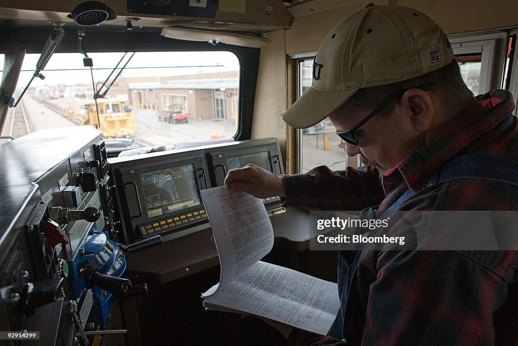
In Madison, it may have gone directly to Norfolk Southern as a “run-through” train, saving the time of reclassification at the frequently-congested TRRA yard. Run-through trains are also subject to less stringent regulations16, meaning more time saved by not conducting a full pre-departure inspection and brake test. Then, a Norfolk Southern crew of one engineer and one conductor would be called. Likely sleep-deprived from several 12-hour shifts in a row, the crew would take a ‘taxi’–really a van from a third-party contractor–to the yard, where they would get their paperwork from the yard office. This paperwork would include:
-a full list of the train’s freight cars, what they’re loaded with, whether that material classified as hazardous or not, what each car’s length and weight is, and its position in the train
-an abbreviated version of the above
-a list specifying all the hazardous chemicals, how they could affect people and/or the environment if leaked, and the responsible party to contact in case of emergency
-a list of track conditions on their route, usually called a Track Bulletin; this would contain slow orders, maintenance curfews, and restrictions specific to the cars in their train
And probably other items specific to Norfolk Southern’s reporting requirements.
The engineer would then check the locomotives, making sure they were signed as ‘inspected’ for that day and starting their diesel engines if necessary. The conductor would walk back to the freight cars and begin “kicking”–releasing–the handbrakes. Then, once they’d returned to the cab of the locomotive, they’d talk to the dispatcher, tell them what train they were, who the crew is and what time they came on duty, what their Bulletin package they had, and what moves they needed to make. The dispatcher would, eventually, give them authority to do so, and they would release the brakes and proceed, doing the least-intensive of the Federally-mandated brake tests16.
The process repeats again in Decatur, the next scheduled crew change point; most likely, only after the crew from Madison has exchanged their Decatur-bound cars for cars that Decatur needs to send further east. This requires another brake test16, but that might not take very long if the cars added to the train have already been brake-tested on their own. The new crew then takes the train to Peru, Indiana, or perhaps even as far as Ft. Wayne, doing more switching at the smallish yard in Lafayette. Then a third crew might take it up to Toledo, diverging from the former Wabash mainline it’s been following thus far and joining the old New York Central’s busy ‘Chicago Line’ at Butler, Indiana. A fourth crew gets the train into Cleveland, likely finishing their day after traversing the east end of the Chicago Line that wraps around downtown, separating it from the shore of Lake Erie by barely half a mile. The fifth–and on this day, final–crew, consisted of an engineer, a conductor, and a conductor trainee, likely hired as part of NS’s attempt to alleviate the crew shortages brought on by the unfettered axing of personnel under PSR23. [Crew change points are conjecture on my part, based on publicly-available employee timetables and my own knowledge of railroad operations.]
Twisted Steel and Fire
And so, at 8:12pm, on that fateful winter evening, train 32N and its 3 crew members passed through Salem, Ohio already doomed. The detector did not trigger an alert, instead simply transmitting its usual message: “Norfolk. Southern. Detector. Milepost. Six. Nine. Point. … No Defects. Repeat. No Defects. Temperature. One. Zero. Eff42. … Detector out.” Sometime between then and 8:54pm, the detector at East Palestine caught the axle, now on fire, and sounded the alarm immediately. “Stop your train,” it said, and the engineer immediately did so, putting the three big locomotives–two up front, and one remote in the middle of the train–into dynamic braking. Seconds later, it happens.
The bearing, pushed beyond all reasonable limits, finally melts and gives way. The truck frame finds itself putting 35,000 pounds of force on an empty space. It buckles, twisting down toward the rail. With nothing keeping the wheel pressed down on the rail, the axle jumps, and the car bounces off the track. Pwosh. The train brakes separate, the triple valves sliding into the emergency position. 90 pounds per square inch of compressed air travel at the speed of sound in both directions from the point where the brake line has come apart, dumping the air out of the emergency reservoir on each car in turn and slamming the brake shoes tight. Thunk-thunk-thunk-thunk-thunk go the cars, as successive braking force yanks the slack out of the couplings. Thousands of tons of steel fly through the air, landing across the ground in a fiery wreck. When it’s all over, 38 cars lie in a burning mass; a symbol of the failure of American railroading.
Conclusion
I can only hope this disaster forces people–the government, the railroads, and the general public–to come to their senses. It’s a miracle that no one was killed in the initial derailment, though the environmental costs will be paid for decades to come. In many ways, East Palestine was inevitable. The systemic failure of railroad companies to allow anything, least of all public safety, to come before ever-increasing profits is the real cause of this wreck, and so long as shareholder-driven Capitalism reigns supreme, I don’t see that ever changing. We can only hope that there won’t be another.
Sources
1 https://www.ntsb.gov/investigations/Documents/RRD23MR005%20East%20Palestine%20OH%20Prelim.pdf
2 https://response.epa.gov/sites/15933/files/TRAIN%2032N%20-%20EAST%20PALESTINE%20-%20derail%20list%20Norfolk%20Southern%20document.pdf
3 https://etd.ohiolink.edu/apexprod/rws_etd/send_file/send?accession=case1168382967&disposition=inline
4 https://pvc.org/pvc-applications/
5 https://en.wikipedia.org/wiki/List_of_weather_records#Temperature
6 https://web.archive.org/web/20070814054640/http://cbwinfo.com/Chemical/Pulmonary/CG.shtml
7 https://apnews.com/article/pennsylvania-ohio-evacuations-fires-5d399dc745f51ef746e22828083d8591
8 https://www.usatoday.com/story/news/local/2023/02/06/east-palestine-ohio-residents-urged-evacuate-after-train-derailment-explosion/69875869007/
9 http://bluford-shops.com/bluford_93_025.htm
10 https://www.law.cornell.edu/cfr/text/49/part-215; see Subpart A, section 215.15; Subpart B, section 215.115; Subpart C, section 215.203; and Appendices A and D
11 https://www.trains.com/trn/train-basics/abcs-of-railroading/wayside-detectors-advancing-fast/
12 https://railfan.com/after-preliminary-investigation-ns-to-inspect-defect-detectors/
13 https://davewisniewski.com/bletdiv4/documents/rules/Pittsburgh%20Division%20TimeTable%202012.pdf
14 https://cs.trains.com/trn/f/111/t/142108.aspx
15 http://www.okthepk.ca/about.htm
16 https://www.ecfr.gov/current/title-49/subtitle-B/chapter-II/part-232/subpart-C?toc=1; see sections 232.205 and 232.207
17 https://www.vice.com/en/article/3angy3/freight-rail-train-disaster-avoidable-boeing
18 https://agtransport.usda.gov/Rail/Rail-Terminal-Dwell-Times/9z94-b4fw/data
19 https://www.theguardian.com/us-news/2023/mar/03/us-rail-workers-east-palestine-ohio-train-crash
20 https://www.freightwaves.com/news/norfolk-southern-eliminated-key-maintenance-role-in-derailment-region-union-says
21 https://sites.google.com/site/trainsymbols/ns
22 https://www.vice.com/en/article/88qze4/32-nasty-rail-workers-say-they-knew-the-train-that-derailed-in-east-palestine-was-dangerous
23 https://www.trains.com/trn/news-reviews/news-wire/norfolk-southern-service-deteriorates-amid-crew-shortages/
24 https://www.newsnationnow.com/us-news/infrastructure/ecp-brakes-technology-ohio-derailment/
25 https://www.youtube.com/watch?v=6YowLAJ-pKA
26 https://railroads.dot.gov/elibrary/ecp-brake-system-freight-services
27 http://www.multimodalways.org/docs/railroads/RRorgs/AAR/AAR%20Interchange%20Rules%20II%201998.pdf
28 https://www.nsk-literature.com/en/railway-industry-bearings/offline/download.pdf
29 https://www.propublica.org/article/norfolk-southern-policy-safety-alerts-east-palestine-derailment
30 https://neversinkmuseum.org/articles/the-life-of-a-brakeman/
31 https://web.archive.org/web/20151017090503/http://pabook.libraries.psu.edu/palitmap/bios/Westinghouse__George.html
32 https://web.archive.org/web/20070626212031/http://www.alkrug.vcn.com/rrfacts/grades.htm
33 https://wplives.org/forms_and_documents/Air_Brake_Principles.pdf
34 http://www.railway-technical.com/trains/rolling-stock-index-l/train-equipment/brakes/north-american-freight.html
35 https://web.archive.org/web/20070626212119/http://www.alkrug.vcn.com/rrfacts/brakes.htm
36 https://web.archive.org/web/20090731183723/http://www.fra.dot.gov/downloads/safety/rail_safety_program_booklet_v2.pdf
37 https://railroads.dot.gov/elibrary/ecp-brake-system-freight-services
38 https://cs.trains.com/trn/b/fred-frailey/archive/2015/05/06/the-war-over-electric-brakes.aspx
39 https://www.trains.com/trn/train-basics/abcs-of-railroading/what-is-precision-scheduled-railroading/
40 https://ctrf.ca/wp-content/uploads/2016/05/CTRF2016CairnsRailTransport.pdf
41 https://www.forbes.com/sites/gurufocus/2012/06/15/bill-ackmans-activist-positions-in-j-c-penney-and-canadian-pacific-railway/?sh=a9c79bc244fd
42 https://www.wunderground.com/history/daily/us/oh/salem/KYNG/date/2023-2-3